
#Diy rgb panel driver#

At the vertical & horizontal end of prototype, I connect anode & all R, G, B pins to long pin male header for later connecting to Led driver board.ĭriver Boards, including: column (layer) scanning (74HC138 + Transistor A1013), row scanning (74HC595 + ULN2803) and Arduino Uno/ Nano. To get an isolated gap between anode and cathode pins, we padded an ABS Round Plastic Pipe when bending led pin. For led matrix column, I also bent the anode pin and connected them like we did with the cathode pins. Finish rows of Led matrix and we need to check every led because at this time, it is easy to fix if there are any broken led or any short circuit between the anode/ cathode pins. Do the same with 2nd row until finish 8th row.

Then, take the R, G, B pins of the first LED in first row and bend it down to the other LEDs and solder the pins which touch each other. Arrange the LEDs in the prototype board in symmetrical form. There are a lot of ways to solder a led matrix that final purpose is connecting all anode pins of the LEDs in columns and the cathode pins (pin Red, Green, Blue) in rows. Decide to purchase RGB Led size & type: For me, I used common anode type with size 5mm. There are a lot of ways to solder a led matrix and I will share my tip to do a led matrix like a compact shield from prototype board: Please follow next step to see my assembly for Led Matrix Board & Driver Board in detail. To do that, Pulse Width Modulation (PWM) is often chosen by using PWM pins on Arduino, beside that B.A.M is a another method to achieve the same thing.įor B.A.M, you can check at my instructables: We know that the brightness of a LED can be controlled by switching it on and off very rapidly. To control an individual color of common anode RGB LED, you set its column HIGH and its corresponding color row LOW. Row scanning: through 3x 74HC595, 3 x ULN2803 for 3 colors: RED, GREEN, BLUE.And then it drive 16 corresponding PNP transistors (A1013). With this combination, it can accept 4 bit binary coded decimal number on its 4 inputs and can select one of its 16 outputs. Column scanning: is done through 2x 74HC138 cascading connection to build 4 to 16 line decoder as diagram above.Driver Board handle column & row scanning to control Led Matrix Board above. Driver Board: are built on a double-side copper prototype PCB 9x15.With my instructables, Led Matrix can be plugged on top of the Driver Board, like a Shield. Led Matrix Board: is built on a single-side copper prototype PCB 9x15.

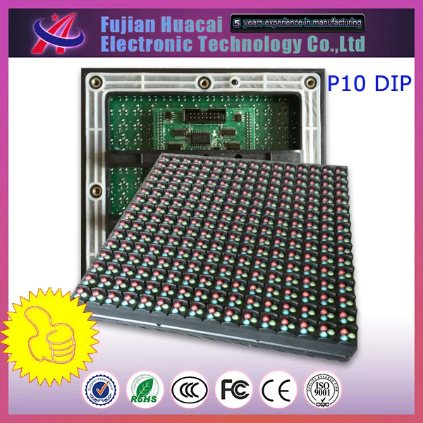
My RGB matrix panel with 128 x RGB LEDs is arranged in 8 rows and 16 columns, including:


 0 kommentar(er)
